Bone Mesh Generation Workflow
This document describes how to build and run MAP Client workflows for generating lower-limb bone meshes from FAI-project mocap data and MRI segmentations.
Background
Generating patient-specific meshes of lower limb bones from FAI data require the fusion of mocap marker data and sparse MRI segmentations. This workflow first uses a statistical shape model of the lower limb to estimate bone meshes from mocap data, then registers the meshes to the segmented surfaces of each bone. Once registered, the meshes can be fitted to the segmented surfaces to improve patient-specificity.
The output meshes (pelvis, femurs, patellas, tibias, fibulas) are used in the OpenSim Model Generation Workflow to produce a patient-specific Gait2392 model.
Inputs Data
- TRC file of mocap static-trial
- Preprocessed segmentations of all the bones
Preprocessing Segmentations
The segmented bone surfaces should only contain vertices on actual bone surfaces. This is because the workflow will be fitting surface meshes to the vertices in the segmentations. If a segmentation has ends that are truncated, check if the truncated ends have been “closed” by the segmentation software. The closing operation tends to introduce vertices “inside” the bone.
- Open a segmented surface in a processing application such as MeshLab.
- View the truncated ends of the surface. They tend to be flat surfaces where the bone has been abruptly cut off.
- Select the faces and vertices on the truncated ends and delete them. In MeshLab, you can use the paintbrush tool to “paint” the faces on the ends and delete the faces with their surrounding vertices.
- Export the modified surface.
Output Data
The workflow described will output two meshes for each bone. One is an STL (or other similar format) file of the patient-specific bone. The other is a GEOF file of the patient-specific bone in an internal format (see Fieldwork Models in the glossary).
Building the Workflow
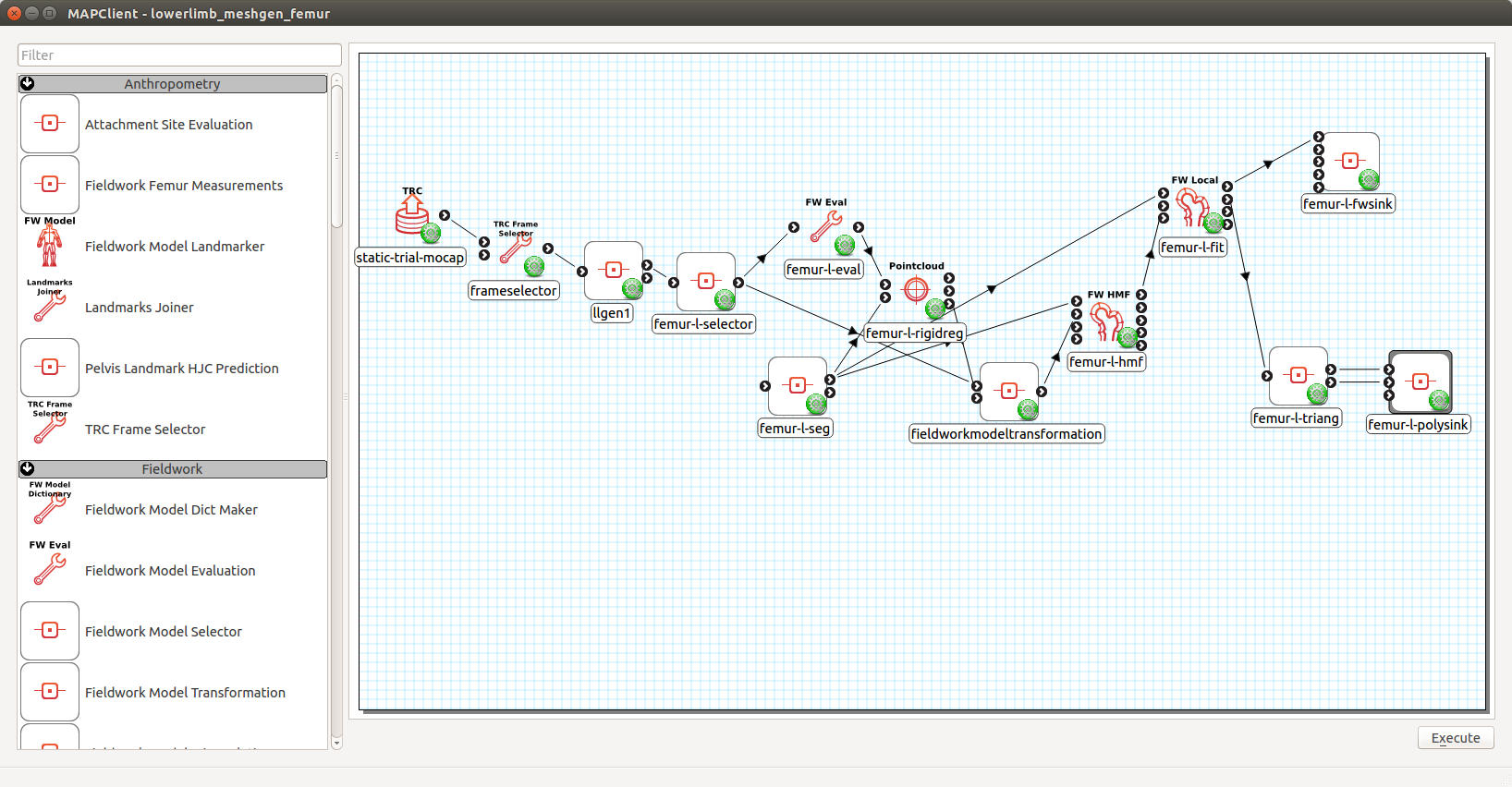
These instructions will create a workflow that produces the meshes for 1 bone for 1 case. The steps can be replicated to output meshes for other bones. Details on each of the plugins/steps used can be found in their respective readme files.
Start a new workflow: File>New>Workflow and create a new folder for the workflow and click Open inside that folder.
Add the TRC Source step to the workspace. Configure it with the case’s static-trial TRC file.
Add the TRC Frame Selector step to the workspace. Connect the output port of TRC Source Step to the first port of TRC Frame Selector Step. Configure the step to read particular frame.
Add the Fieldwork Lower Limb (2 sides) Generation step to the workspace. Connect the output port of TRC Frame Selector Step to the input port. Configure the step:
- PCs to Fit: 1
- Mahalanobis Weight: 0.1
- Landmarks:
- femur-HC-l : LHJC
- femur-HC-r : RHJC
- femur-LEC-l : LLFC
- femur-LEC-r : RLFC
- femur-MEC-l : LMFC
- femur-MEC-r : RMFC
- pelvis-LASIS : LASI
- pelvis-LPSIS : LPSI
- pelvis-RASIS : RASI
- pelvis-RPSIS : RPSI
- tibiafibula-LM-l : LLMAL
- tibiafibula-LM-r : RLMAL
- tibiafibula-MM-l : LMMAL
- tibiafibula-MM-r : RMMAL
- Marker Radius: 5 (or whatever the marker radius was, unit is mm)
- Skin Padding : 5 (or whatever the patient soft-tisse was roughly, unit is mm)
- Knee Options : check Abd. DOF
- GUI : check
Add the Fieldwork Model Selector step to the workflow. If you do not have this plugin, you will need to installed it from the plugins Github site. Follow the instructions in the Plugins/Manually section in MAP Client Installation. Connect the first output port of the Fieldwork Lower Limb (2 sides) Generation step to the input port. Configure the step:
- identifier should contain the name of the bone to be generated, e.g. femur-l-selector.
- Model Name should be one of:
- pelvis
- femur-l
- femur-r
- patella-l
- patella-r
- tibiafibula-l
- tibiafibula-r
Add the Fieldwork Model Evaluation step to the workspace. Connect the output port of the Fieldwork Model Selector step to the input port. Configure the step:
identifier : something like femur-l-eval
discretisation: [10,10]
node coordinates: False
elements: the elements sampled should be where the segmented surfaces are on each bone. Therefore, the elements are different for each bone.
- Pelvis: 27-47, 64-67, 72, 100-120, 137-140, 145
- Femurs: all
- Patellas: all
- tibiafibulas: 0-2, 10-23, 52-54, 72-83
Add the Pointwise Rigid Registration step to the workspace. Connect the output port of the Fieldwork Model Evaluation step to the first input port. Configure the step:
- identifier: something like femur-l-rigidreg
- UI Mode: check
- Registration Method: ICP Rigid Target-Source
- Min Relative Error: 1e-6
- Points to Sample: 1000
Add the Polygon Source step to the workspace. Connect its first output port to the second input port of the Pointwise Rigid Registration step to the. Configure the step:
- identifier: something like femur-l-seg
- File format: auto
- Filename: the filename of the segmented surface of the bone.
Add the Fieldwork Model Transformation step to the workspace. Connect the second output port of the Pointwise Rigid Registration step to the second input port. Connect the output port of the Fieldwork Model Selector step to the first input port. This step does not need any configuring.
Add the Fieldwork Host Mesh Fitting step to the workspace. Connect the first output port of the Polygon Source step to the first input port. Connect the output port of the Fieldwork Model Transformation step to the second input port. Configure the step:
- identifier: something like femur-l-hmf
- GUI: True
- fit mode: DPEP
- host element type: quad444
- slave mesh discretisation: [10,10]
- slave sobelov discretisation: [4,4] ([5,5] for the femur mesh)
- slave sobelov weight: [1e-5, 1e-5, 1e-5, 1e-5, 2e-5]
- slave normal discretisation: 4 (5 for femur mesh)
- slave normal weight: 100
- max iterations: 5
- host sobelov discretisation: [4,4,4]
- host sobelov weight: 1e-5
- n closest points: 1
- kdtree args: {}
- verbose: True
Add the Fieldwork Mesh Fitting step to the workspace. Connect the first output port of the Polygon Source step to the first input port. Connect the output port of the Fieldwork Host Mesh Fitting step to the second input port. Configure the step:
- identifier: something like femur-l-fit
- GUI: True
- fit mode: DPEP
- mesh discretisation: 5.0
- sobelov discretisation: [4,4] ([5,5] for the femur mesh)
- sobelov weight: [1e-4, 1e-4, 1e-4, 1e-4, 2e-4]
- normal discretisation: 4 (5 for femur mesh)
- normal weight: 100
- max iterations: 2
- max sub-iterations: 2
- xtol: 1e-6
- n closest points: 1
- kdtree args: {}
- verbose: True
- fixed nodes: none
Add the Fieldwork Model Triangulation step to the workspace. Connect the first output port of the Fieldwork Mesh Fitting step to the input port. Configure the discretisation to a desired density, e.g. 10,10.
Add the Polygon Serialiser step the to workspace. Connect the first and second output ports of the Fieldwork Model Triangulation step to the first and second input ports, respectively. Configure the step:
- identifier: something like femur-l-polysink
- File Format: STL (or another format as desired)
- Filename: the file path to write the bone’s STL file. E.g. /case_xx/fitted_meshes/femur-l.stl
Add the Fieldwork Model Serialiser step to the workflow. Connect the first output port of the Fieldwork Mesh Fitting step to the first input port. Configure the step:
- identifier: something like femur-l-fwsink
- GF Filename: the file path to write the bone’s Fieldwork model .geof file. E.g. /case_xx/fitted_meshes/femur-l.geof
To fit another bone in the same workflow, create a branch in the workflow by repeating steps 5 to 15. Remember to name the identifier of each new step according to the new bone’s name and configure the Model Name parameter in the Fieldwork Model Selector step to be that of the new bone.
Running the Workflow
When the workflow is executed, the workflow steps are executed from start to finish. The steps are explain below. Most steps are automatic and do not have user interaction. They are denoted by [AUTO]. The operation of the other steps are explain below. For more details on each step’s operation, please refer to their respective readme files.
[AUTO] The TRC Source step read in the case’s static-trial marker data.
[AUTO] The TRC Frame Selector step extracts the marker names and locations at a specified frame.
The Fieldwork Lower Limb Generation step registers the lower-limb shape model to the specified markers, thereby generating approximately patient-specific meshes for each lower limb bone.
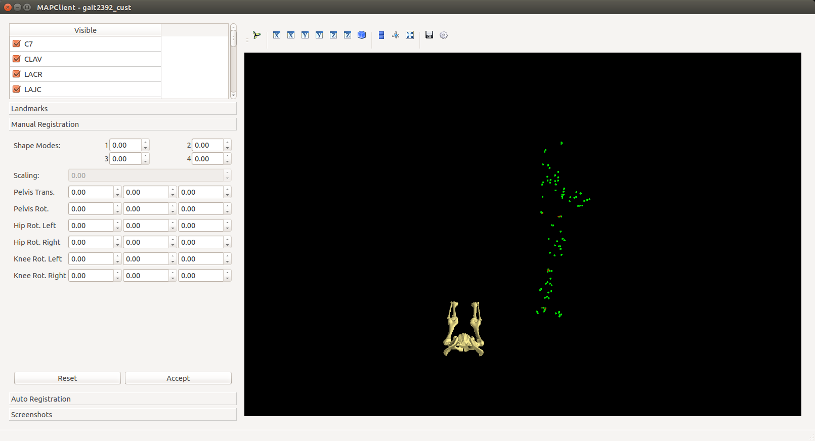
When the GUI of this step appears, the lower limb model will be shown in its un-registered position away from the green markers. The step is preconfigured so simply click the Register button in the Registration tab. Registration will take around 2 minutes after which the model will be registered with the markers. The registration can be refined by increasing the PCs to Fit value to 5 and clicking Register again. Model parameters can be manually adjusted in the Manual Registration tab. Click Accept to move onto the next step.
[AUTO] The Fieldwork Model Selector step picks a specified bone mesh from the lower limb model.
[AUTO] The Fieldwork Model Evaluation step discretises the selected mesh into a pointcloud for registration to the segmented surfaces.
[AUTO] The Polygon Source step reads in the segmented surfaces.
The Pointwise Registration step performs a rigid-body registration of the mesh pointcloud (5) to the segmented surface.
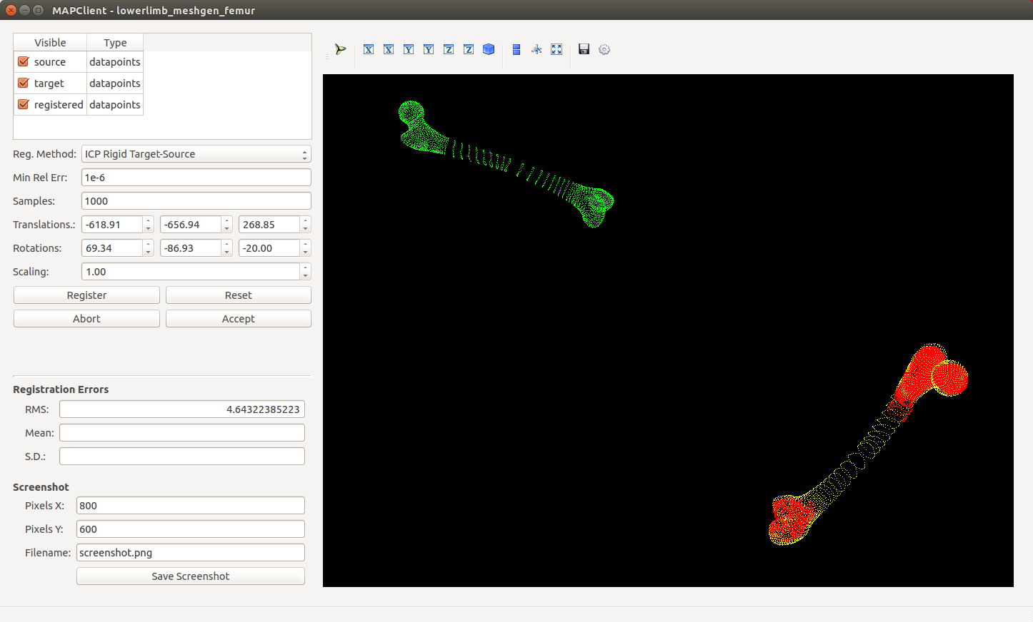
When the GUI of this step appears, the source pointcloud (discretised mesh) is shown in green and the target in red (segmented). Play with the Euler Rotation angles until the yellow pointcloud (registered source) is roughly in the same orientation as the target, then click Register to perform an automatic ICP registration. The registration can be manually adjusted through the Translation and Rotation values. Click Accept to move onto the next step. [KNOWN BUG] Error messages concerning VTK will appear when the registered pointcloud updated in the 3-D viewer. This message can be ignored.
[AUTO] The Fieldwork Model Transformation step applies the rigid-body registration transformation from (7) to the bone mesh from (4) to register it to the segmentation.
The Fieldwork Host Mesh Fitting Step performs a host-mesh fit of the bone mesh to the segmentation to bring the mesh a bit closer to the segmentation before local mesh fitting.
The step is preconfigured so click Fit to start the fit. Fitting will take 1-2 minutes. After the fit finishes, you can click Fit again to improve the fit. A RMS error of less than 2.5 mm should be sufficient. Click Accept to move onto the next step.
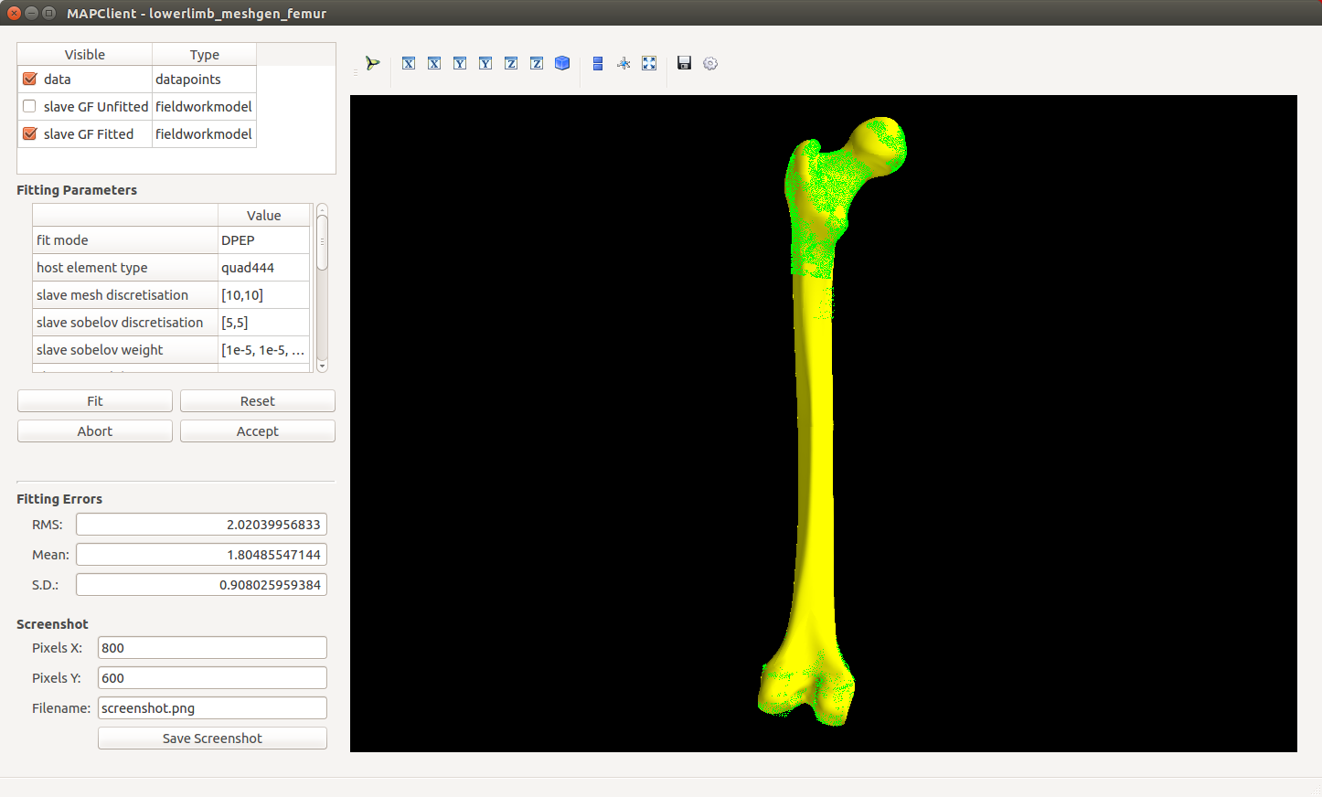
The Fieldwork Mesh Fitting Step performs a final local mesh fit of the bone mesh to the segmentation.
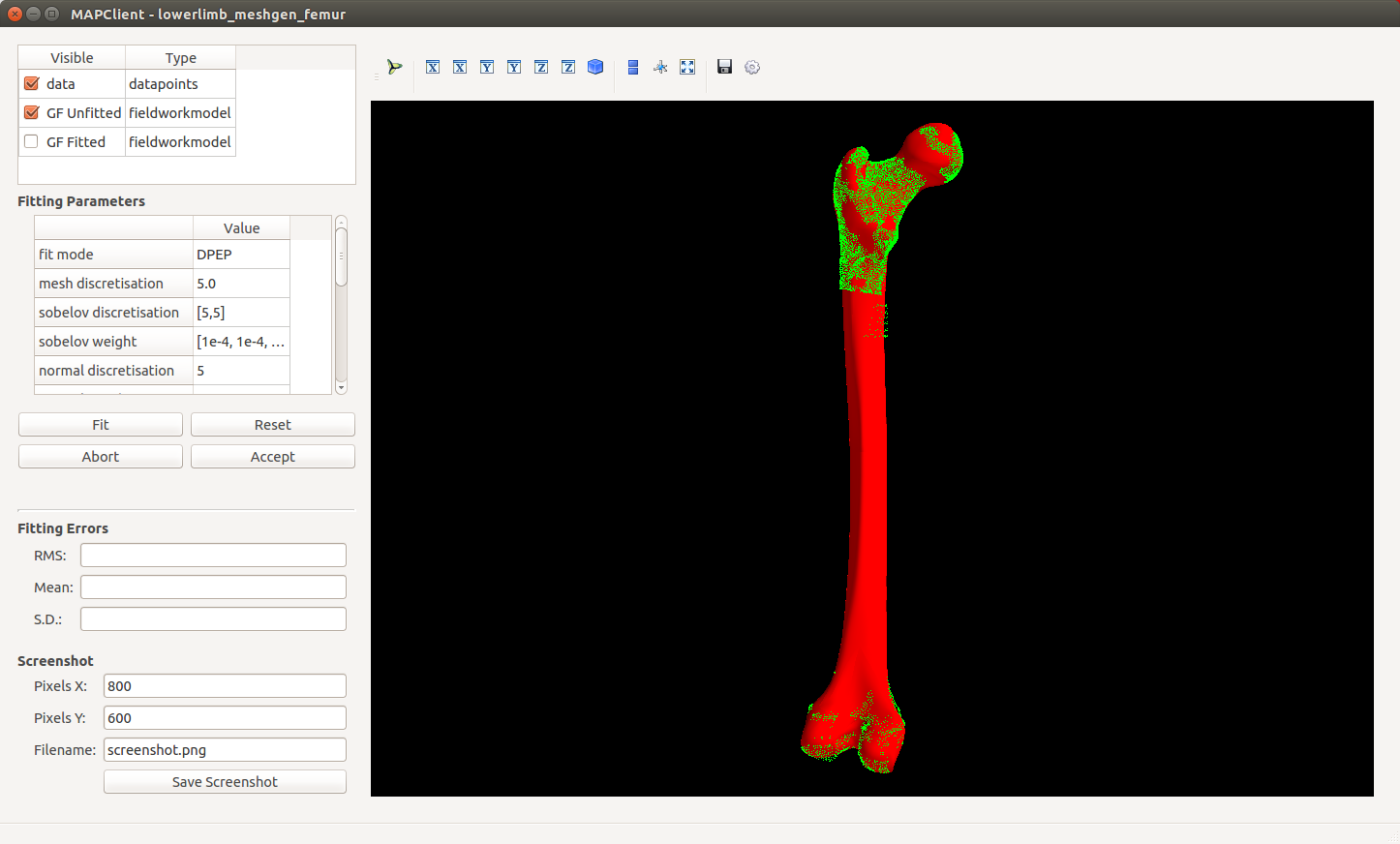
The step is preconfigured so click Fit to start the fit. Fitting will take 1-15 minutes depending on the size of the mesh (Pelvis will take the longest). After the fit finishes, you can click Fit again to improve the fit. A RMS error of around 1 mm should be sufficient. Click Accept to move onto the next step.
[AUTO] The Fieldwork Model Serialiser step writes the fitted mesh to file in the internal .geof format.
[AUTO] The Fieldwork Model Triangulation step discretises the fitted mesh into a triangulated surface mesh with the configured discretisation level.
[AUTO] The Polygon Serialiser step writes the triangulated surface mesh to file in the specified format (e.g. STL).
When the workflow is complete, MAP Client will return to the workspace view.